Kyoto University’s Harada Lab Leads Open-Source mmWave Local 5G System with TMYTEK’s Enabling Technologies
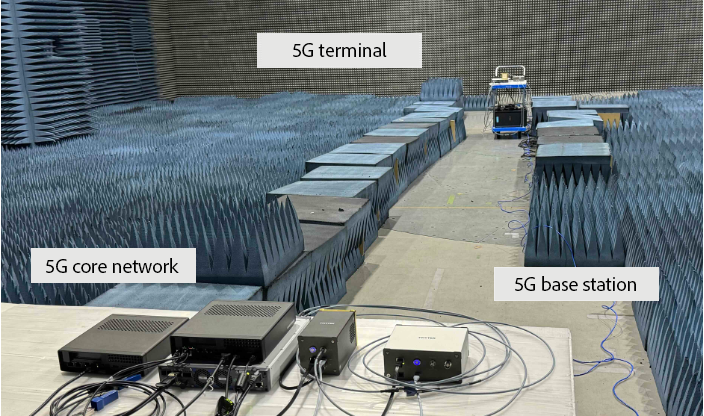 Figure 1: Architecture of the Millimeter-Wave Local 5G Software-Defined Radio System
Source: Harada Laboratory – https://www.dco.cce.i.kyoto-u.ac.jp/en/PL/PL_2024_08.html
Background and Technical Challenges in mmWave Local 5G Systems
With the advancement of 5G NR and the upcoming 6G era, wireless systems are transitioning toward higher frequency bands, particularly the millimeter-wave (mmWave) spectrum. These frequencies offer large bandwidth but present critical challenges in propagation loss, signal directivity control, and efficient spectrum usage.
Key Challenges in mmWave Deployment:
1. Severe Signal Attenuation
a. Short wavelengths of mmWave signals result in limited penetration through obstacles.
b. Significant path loss occurs over distance, reducing communication stability in non-line-of-sight (NLOS) environments.
2. Need for High-Precision Beam Control
a. Real-time beam alignment is required to maintain directional links in 5G NR systems.
b. Advanced beam tracking is essential for supporting mobility and dynamic coverage.
3. Limited Spectral Efficiency due to OOBE
a. CP-OFDM, the standard 5G waveform, causes out-of-band emissions (OOBE), affecting adjacent channels.
b. Novel waveform processing, such as UTW-OFDM, is needed to suppress OOBE and improve spectrum usage.
4. High Cost and Complexity of mmWave Testing
a. Conventional mmWave equipment is bulky, expensive, and not scalable for iterative research.
b. A modular, software-integrated test platform is needed to support applications like smart cities, autonomous vehicles, and industrial private 5G.
To address these, the research team developed a complete mmWave local 5G system that includes: Core Network (5GC), Base Station (gNB), User Equipment (UE)To address these, the research team developed a complete mmWave local 5G system that includes: Core Network (5GC), Base Station (gNB), User Equipment (UE)
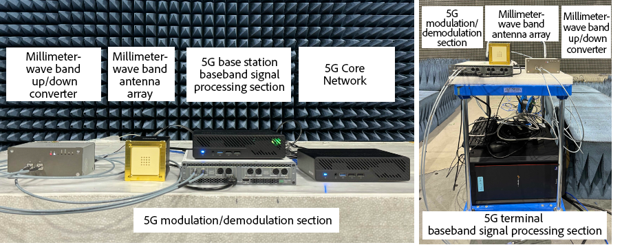 Figure 2: The developed millimeter-wave local 5G software radio system (Left: base station (gNB) and core network (5GC), Right: terminal (UE))
Source: Harada Laboratory – https://www.dco.cce.i.kyoto-u.ac.jp/en/PL/PL_2024_08.html
This system integrates software-defined radio (SDR) technology with TMYTEK mmWave RF front-ends for flexible experimentation and validation.
System Solution: Building a Flexible mmWave Platform with TMYTEK 5G/6G Testbeds
To realize a flexible, scalable, and affordable mmWave testing platform, the research team adopted open-source 5G software from OpenAirInterface (OAI), integrated with TMYTEK’s 5G Testbeds, BBox and UD Box modules, to overcome the limitations of traditional mmWave platforms.
TMYTEK BBox – Precision Beamforming for mmWave
- A 28 GHz beamformer with a 4×4 antenna array (16 elements)
- Supports ±45° beam steering in both azimuth and elevation
Advantages:
- Fine-grained control enables precise beam alignment, with 360° phase coverage at 5° steps and gain tuning at 0.5 dB resolution—enhancing link quality in mmWave systems
- Seamlessly interfaces with OAI 5G NR software for real-time TX/RX beam control
- Modular design enables deployment in various application scenarios (e.g., smart factories, V2X)
TMYTEK UD Box – mmWave Frequency Up/Down Conversion
- Supports frequency conversion from baseband to 28 GHz (up to 44 GHz)
- Equipped with low-noise and high-gain architecture for maintaining signal integrity
Advantages:
- Integrates directly with SDR platforms, minimizing system complexity
- Enables cost-efficient testing with PCs and SDRs
- Forms a complete mmWave testbed when paired with BBox
Both devices are equipped with an open API, supporting Python, LabVIEW, MATLAB, and C++, facilitating smooth integration and reducing the development cycle for 5G researchers.
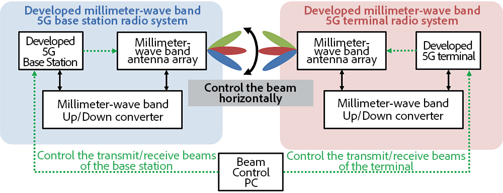 Figure 3: Overview of the developed system.
Source: Harada Laboratory – https://www.dco.cce.i.kyoto-u.ac.jp/en/PL/PL_2024_08.html
Experiment Results: Beamforming and Spectrum Efficiency Validation
The system was tested under controlled conditions to evaluate beam alignment, throughput performance, and spectral efficiency using both CP-OFDM and the proposed UTW-OFDM scheme.
UTW-OFDM Spectrum Efficiency Evaluation
To mitigate the out-of-band emissions (OOBE) inherent in CP-OFDM, the research team developed UTW-OFDM (Ultra-Time Window OFDM).
- It applies waveform shaping over extended time windows to effectively suppress spectral leakage and reduce interference to adjacent bands.
- Experimental results confirm that UTW-OFDM significantly reduces OOBE and enhances spectrum utilization compared to CP-OFDM.
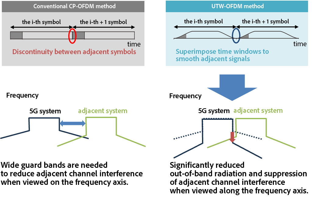 Figure 5: Overview of UTW-OFDM Scheme
Source: Harada Laboratory – https://www.dco.cce.i.kyoto-u.ac.jp/en/PL/PL_2024_08.html
mmWave Communication Performance Test
Environment: Anechoic chamber
Distance: 9 meters between base station and terminal
Bandwidth: 50 MHz
Key Results:
- Max downlink (BS → UE): 50 Mbps
- Max uplink (UE → BS): 38.2 Mbps
- 0° alignment achieved peak throughput.
- ±15° offset caused notable performance drop.
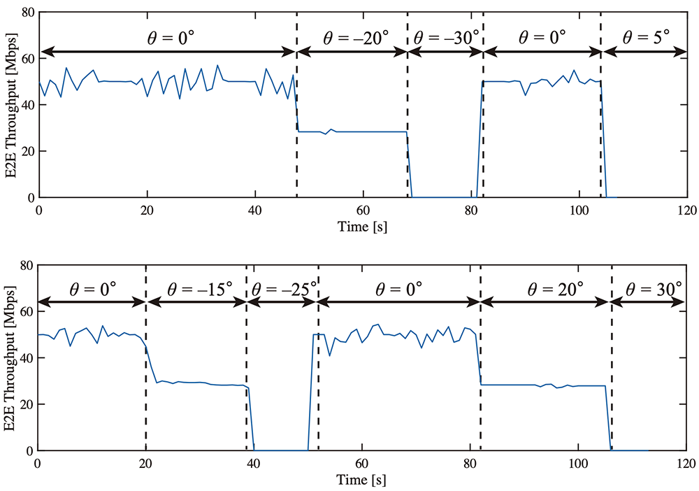 Figure 4: Relationship between antenna directivity and data rate of base stations and terminals (Top: directivity of the transmit antenna beam of the base station/ Bottom: directivity of the receiving antenna beam of the terminal)
Source: Harada Laboratory – https://www.dco.cce.i.kyoto-u.ac.jp/en/PL/PL_2024_08.html
Conclusion: TMYTEK Enables Practical and Scalable mmWave 5G Prototyping
The research team implementation demonstrates that TMYTEK’s 5G/6G Testbeds, BBox and UDBox modules:
- Enable accurate beam tracking, essential for mmWave stability
- Lower the barrier to entry for local 5G R&D by simplifying testbed construction
- Support advanced waveform research, such as UTW-OFDM, for future 6G applications
- Provide a compact, flexible, and cost-effective mmWave Testbed adaptable to multiple scenarios
By integrating modular hardware with open-source SDR software, Harada’s Lab successfully validated a mmWave 5G system that can adapt to future communication demands. TMYTEK’s contributions were crucial in realizing a scalable test environment that accelerates research in next-generation wireless technologies.