5G mmWave small cells – Pathways to growth in mmWave capable small cell solutions

5G mmWave small cells – Pathways to growth in mmWave capable small cell solutions
Produced by the SCF Components and Products group, this new white paper provides a comprehensive overview of the evolving landscape of 5G mmWave small cells, examining both the current state of deployments and the promising avenues for future development.
This white paper provides a comprehensive overview of the evolving landscape of 5G mmWave small cells, examining both the current state of deployments and the promising avenues for future development.
Part of introduce about Link Budget and Antenna Desgin.
6. OptimizingmmWavefor5GNRsmallcells
In 5G mmWave bands, link budgets and effective isotropic radiated power (EIRP) calculations are essential for designing and optimizing wireless communication systems, due to the propagation impairments.
This section discusses link budgets, EIRP power considerations, and the significance of beamforming technology in mmWave 5G.
6.2 Link Budget
The link budget plays a vital role in telecommunications and communication systems by evaluating the power budget of a communication link. It aids in assessing the adequacy of received signal power for dependable communication and estimating achievable communication distances based on the radio performance of transmitting and receiving equipment. Moreover, it takes into account the impact of the transmission medium and environmental factors.
The basic link budget equation is:
LFS = PTX + GTX - LTX + GRX - LRX - PRX - LENVIR
Where:
LFS:free space propagation loss (dB) or MAPL (maximum allowed path loss)
PTX:outpower of transmitter (dBm)
GTX:gain of transmitting antenna (dB)
LTX:loss of entire transmitter path (dB) (connectors, cables...)
PRX:received power or receive sensitivity of receiver (dBm)5F6
GRX:gain of receiving antenna (dB)
LRX:loss of entire receiver path (dB) (connectors, cables...)
LENVIR:loss of environmental effects (km/dB) (humanity, weather, atmosphere...)
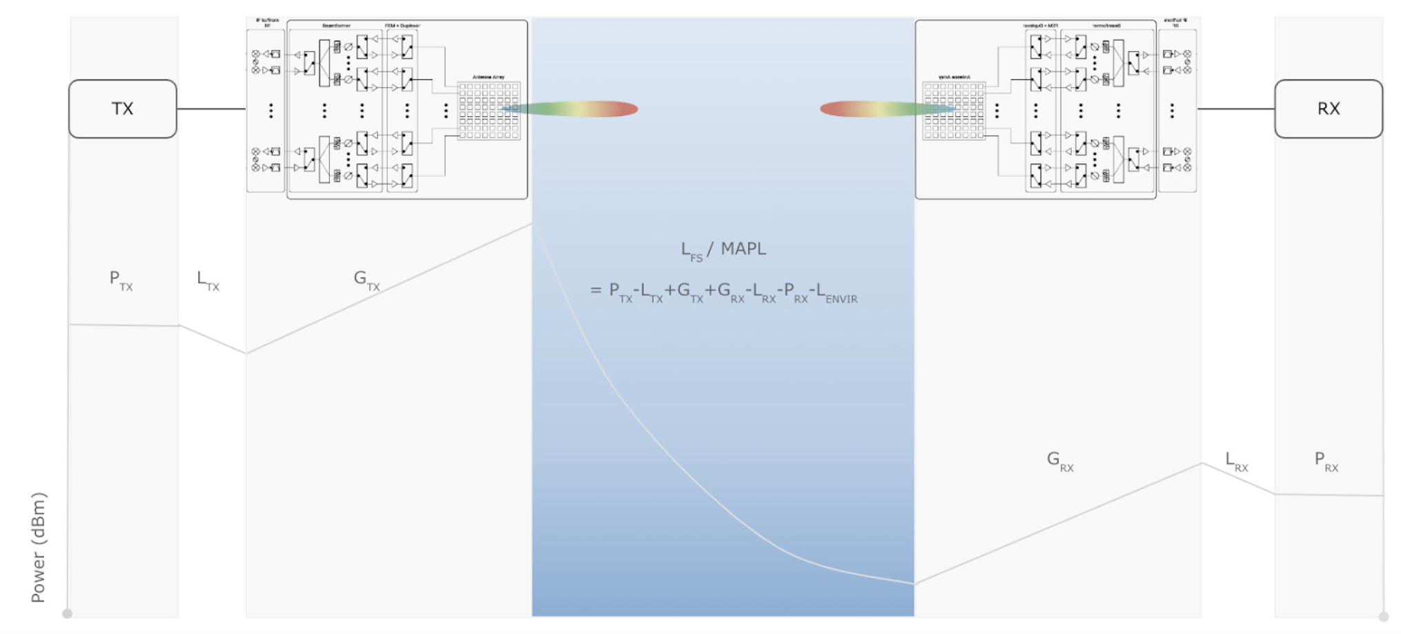 Figure 6–1 Link budget calculation graph in communication path
7.8 mmWave antenna
The design of mmWave antenna arrays involves critical principles to ensure optimal performance, beamforming capabilities, and efficient communication in the mmWave frequency bands.
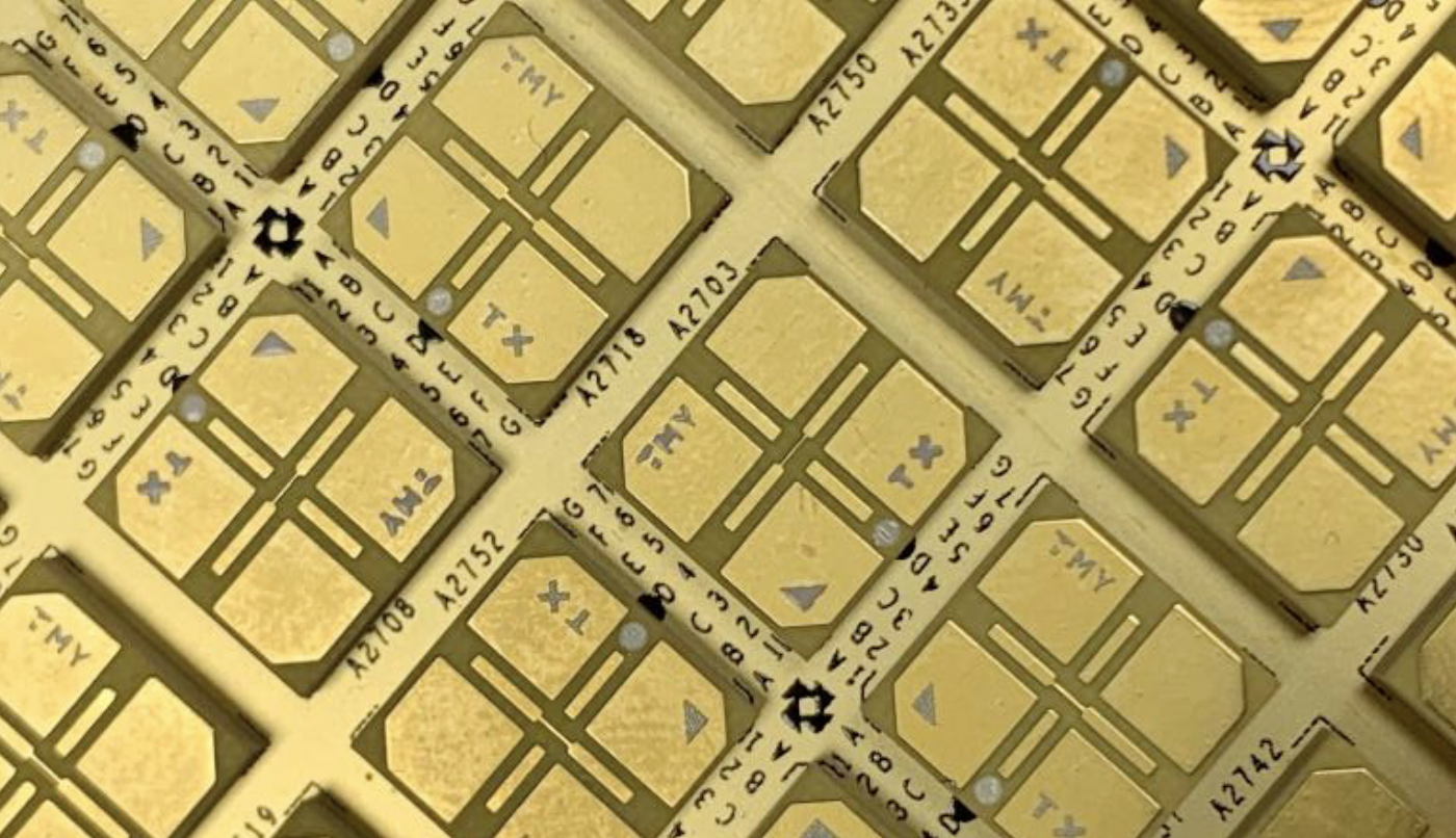 Figure 7–10 Example mmWave antenna array (TMYTEK)
The key design principles for mmWave antenna arrays are detailed below:
Antenna Element Design
- Design individual antenna elements for efficient operation at mmWave frequencies.
- The symmetry design is important to address factors such as gain, radiation pattern, polarization, and impedance matching.
- Select the appropriate polarization such as horizontal, vertical or cross- polarization based on the application requirements.
- Antenna dimensions and characteristics are influenced by the targeted frequency bands, and wideband is a basic requirement for mmWave.
- Compact antenna design is particularly critical for small cells.
Antenna Array Design
- The spacing is typically a fraction of the wavelength to achieve desired beam characteristics, and to optimize the spacing between antenna elements to create constructive interference and beamforming.
- Design the array geometry based on the application and desired beamforming capabilities to generate beam shape and suppressed side lobe.
- Linear arrays, planar arrays, and other geometries offer different trade-offs in terms of directivity and coverage.
- Proper feed network design for large array matrices ensures uniform excitation of elements and minimizes losses.
Future details on antenna array technology are described in the Appendix.