3GPP Compliant Beam Switching: Based on SPI Control of BBox
Overview
Millimeter wave in 5G
Millimeter wave (mmWave) promises the vision of 5G communication with the challenge of high path loss. To resolve the loss, a phased array is the solution by gathering the energy with array elements. Therefore, beamforming and beam control technologies come into play due to the nature of the directional radiation pattern of the array antenna. To increase the coverage, we need beamforming and beam steering technologies to point the beam toward a specific direction depending on the scenario.
Fast beam steering is necessary
In 3GPP, base stations perform beam sweeping with 64 Synchronization Signal Block (SSB) in one SS burst set for mmWave in 5 ms to trigger UEs reporting beam quality based on the Reference Signal Received Power (RSRP). Although each beam takes 78.125 μs to switch, this also includes other protocol stack processing, which means the actual beam switching control may take only a fraction of the 78.125 μs timeframe.
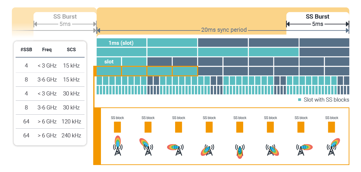 Figure 1. Grid of SSB Beams in 5G NR, Beam Switching Procedure
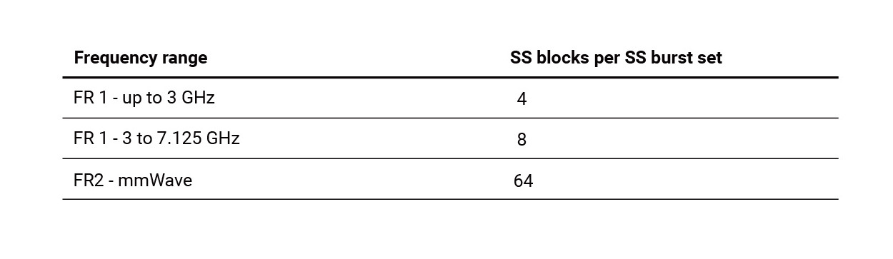
The number of SS blocks in one SS burst set depends on the operating frequency. For mmWave, it needs to contain 64 Synchronization Signal Blocks in 3GPP definitions.
Another time-critical task is beam shaping by beam refining procedures which occur after beam sweeping in order to point out a target UE precisely. The new feature of TMYTEK BBox SPI control satisfies the fast beam control requirements for MIMO and beam management as described in the above sections. For researchers or developers of 5G NR algorithms, such as beam tracking, having a piece of convenient equipment to create the communication path in the real world is necessary. But most of the time, this kind of product is neither flexible enough to fit your system nor does it meet developers or researchers’ requirements.
Veriy SPI Interface
We designed the following experiment to visualize the speed of SPI control and to show users how it operates.
Experiment
USRP is a popular SDR platform for 5G developers with the following architecture block diagram. A host (PC) to schedule the communication procedures and coordinate time-critical relevant parts operating on the FPGA to speed up the whole communication process.
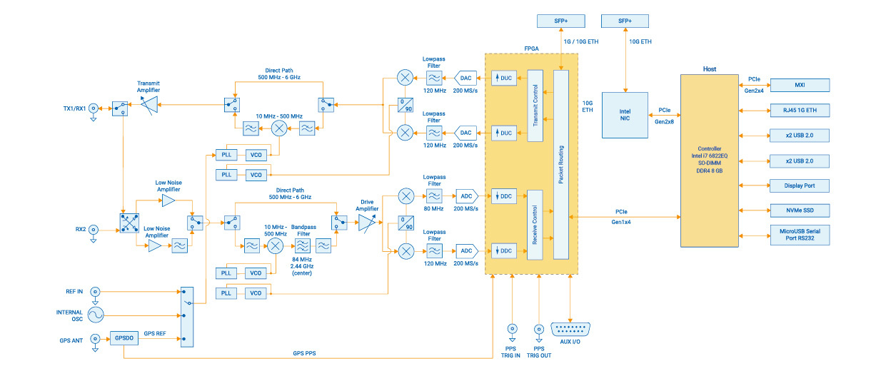 Figure 2. USRP 2974 System Block Diagram
TMYTEK BBox is a powerful tool for developing the protocol. Depending on the scenario (time-critical or not), users can use the API to switch the control interface between LAN port and SPI interface.
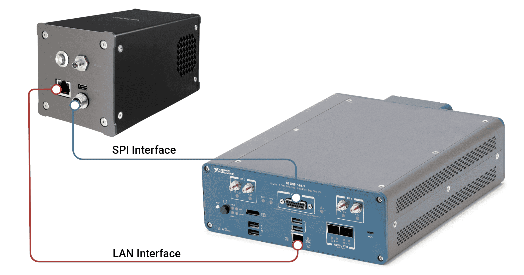 Figure 3. Control Interfaces Between BBox and SDR
The integration of BBox and SDR is straightforward, LAN to LAN and SPI to SPI.
Experiment setup
System Architecture
The system contains 2 main parts, one is using LAN control for preconfig beam pattern control parameters for specific beamId. The second part is related to triggering a beam pattern through SPI by FPGA.
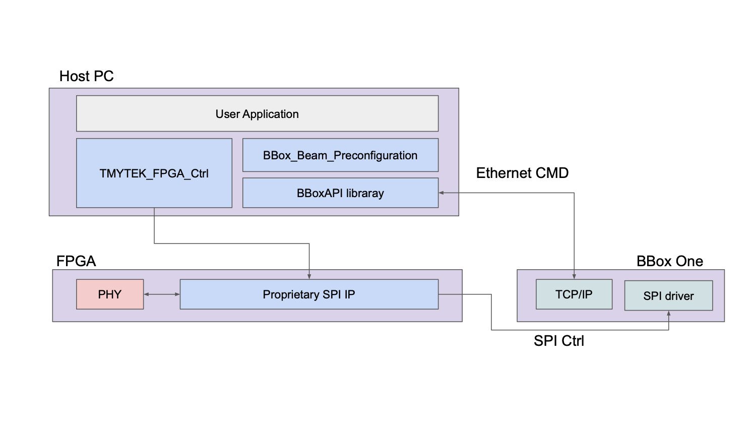 Figure 4. Software System Architecture of Experiment
Step-by-step
- Connect the proprietary cable to a BBox 5G device and the other side connects to USRP FPGA output pins. It may connect to the client’s specific FPGA.
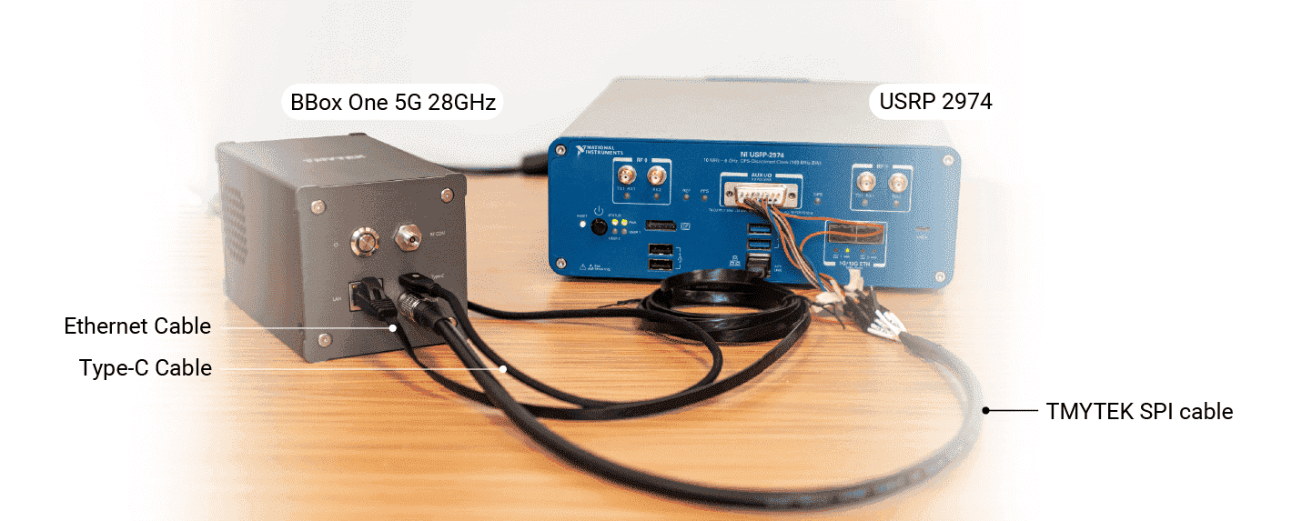 Figure 5. Connection between SDR and BBox One 5G 28GHz* Connect USRP host and a BBox 5G device using an Ethernet cable.
 - Configure the FPGA SPI clock speed to 20MHz.
- Up to 64 pre-configured beams, the beam patterns can be configured on the host device by connecting an Ethernet cable to BBox One/Lite. For adjacent beamId, such as beamId_1 and beamId_2, we deliberately set a difference in power output between them for ease of distinguishing the two. You can configure the beam pattern by triggering FPGA to output specific control patterns. In this example, we will alternately trigger beamId_1 and beamId_2 patterns.
- Use an oscilloscope to monitor the output power of a single channel on the BBox device, and then observe the duration of power variation, we expect the duration to be under 100 μs.
- Verify the result of the beam control, measuring the pattern in CATR is optional.
- Figure 6. shows the whole settings of this experiment. The TMYTEK UDBox converts the signal from 28GHz into 100 MHz for observation.
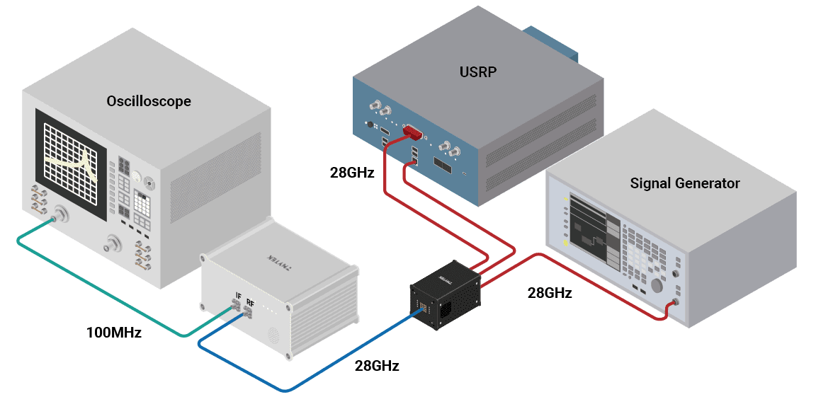 Figure 6. Experiment Setup Diagram
Summary
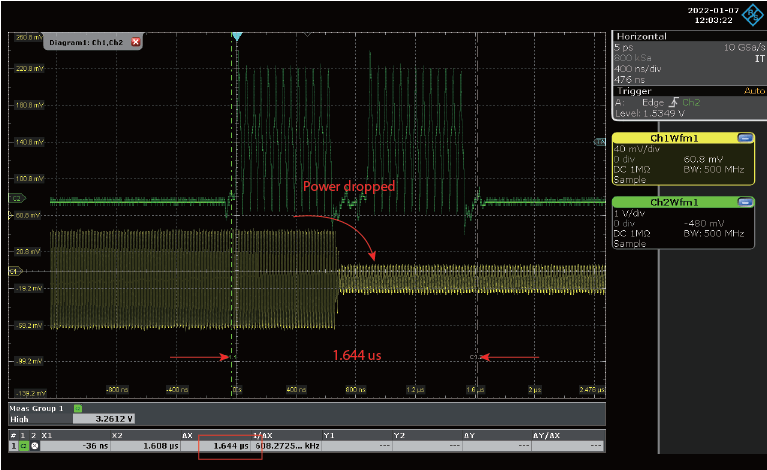 Figure 7. The Waveform of SPI Control Clock and Output Power at One Channel
Due to different output power for different beamId, we expected to see a periodic power output difference. This difference in power helps us to observe the beam steering results with ease. From figure. 7, the SPI control clock is shown in channel 2. The output power of a specific channel of BBox is shown in channel 1. We can observe that there is a periodic power pattern that represents the beam switching period. It takes 1.65 μs for each beam steering.
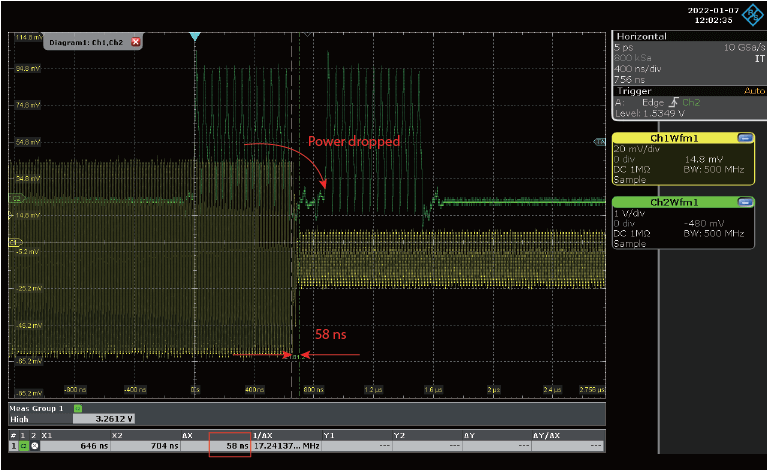 Figure 8. Transition Timing
Figure 8 shows that the transition time is around 60 ns under 20 MHz SPI clock. The experiment results show that TMYTEK BBox can be used in those time-critical user scenarios and help developers perform beamforming within an extremely short time. From the observation above, it shows the beam switching performance fits the 3GPP defined criteria.
Download 3GPP Compliant Beam Switching: Based on SPI Control of BBox Application Note >>