Fast, mmWave Over-the-Air Testing
POSTED ON DECEMBER 7, 2022 BY TMYTEK
A phased array antenna aggregates many antenna elements to form a large array that uses beamforming to increase the directional gain, with the effective isotropic radiated power (EIRP) characterizing the power and reach of the phased array. The directional gain compensates for signal fading, enabling applications to benefit from mmWave’s high bandwidth and low latency. As such, phased arrays have been widely adopted for 5G and satcom applications, with MIMO, multi-user MIMO (MU-MIMO) and massive MIMO (mMIMO) architectures enabled by beamforming and beam steering technologies to increase network capacity and improve the user’s experience.
To minimize size and achieve the best performance, many systems adopt the compact antenna-in-package (AiP) architecture, where the phased array antenna and components such as beamformers, power amplifiers and up- and down-converters are all integrated (see Figure 1). The only way to test a mmWave AiP system is OTA, since the AiP system is a single, compact package with many RF channels and no RF connectors at the antenna elements. Beam steering is a key factor for successful performance. To guarantee beam steering performance, OTA testing must evaluate the AiP’s characteristics, such as radiation pattern and the relative gain and phase of the elements.
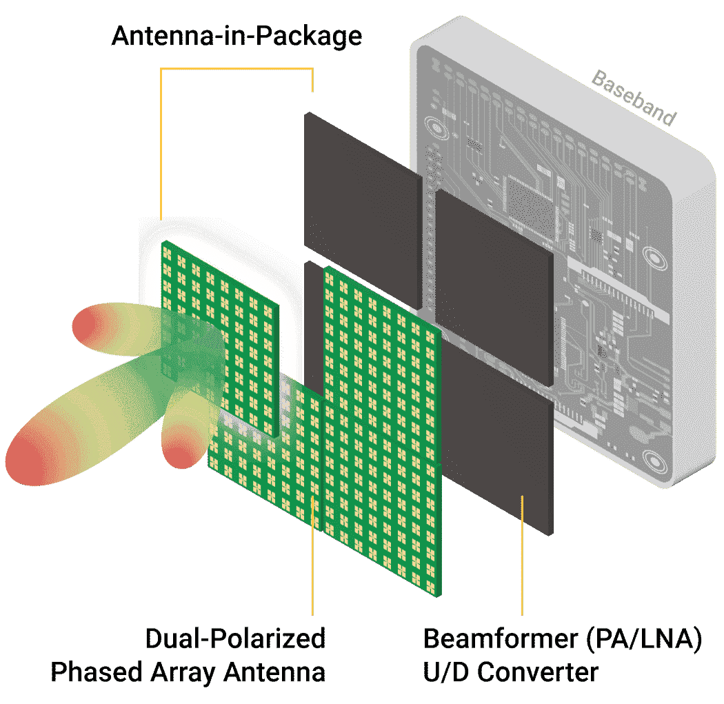 Figure 1 AIP system construction. Source: pSemi
TRADITIONAL OTA TESTING
With the adoption of 5G and satcom, more systems and devices are moving to mmWave frequencies. Depending on the system architecture and antenna design, devices for these applications have varying sizes and shapes; OTA measurement of the antenna system requires an anechoic test chamber, where the size of the chamber depends on the size of the device. For 5G systems, several measurement options are defined by 3GPP:
Far-Field Measurement Options
The 3GPP TR 38.810 specification defines the direct far-field (DFF) technique, which requires a minimum measurement distance (see Figure 2), where the spherical wave from the source is transformed into a plane wave for radiation pattern measurements. The DFF method generally requires larger test chambers based on the diameter and operating wavelength of the AiP module. For example, a 28 GHz device with an antenna dimension of 15 cm requires a 4.2 m chamber to achieve far-field measurements. The larger the chamber, the higher the cost, the greater the space and added test time due to the mechanical operation of the chamber.
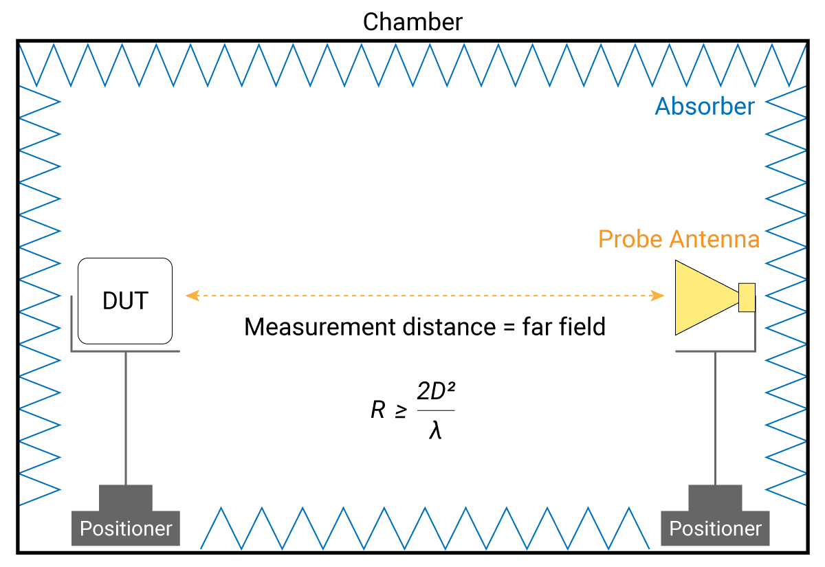 Figure 2 Direct far-field test setup.
A compact antenna test range (CATR) uses the indirect far-field (IFF) method to reduce the size of the test chamber (see Figure 3). The CATR system uses a parabolic reflector to parallelize the wave from the feed horn to create a far-field test environment. Although the distance between the device under test (DUT) and the feed antenna is essentially halved, the entire CATR system still requires a chamber box of significant dimensions. In addition to chamber size, the CATR setup slows measurement time, typically taking 10 to 20 minutes.
To measure a 3D sphere radiation pattern, the testing methods for traditional DFF chambers and IFF CATR include rotating the DUT in azimuth and elevation to obtain full pattern measurements. This requires the DUT to be mounted on a rotating table stepped by electric motors, often taking hours to generate a complete 3D antenna pattern—with the potential for interference or other limitations caused by the motors.
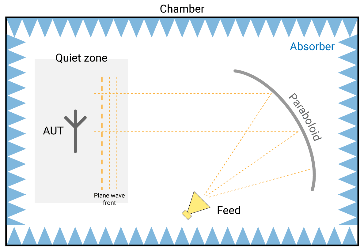 Figure 3 Indirect far-field test setup using a CATR.
Horn Antenna Measurements
AiP testing using a horn antenna is faster and more cost-effective for mass production testing (see Figure 4). However, it only measures the total radiation peak power at a fixed angle. Even with three horn systems, each horn in a different position, the testing angles and dimensions are limited. Since the AiP is a phased array with many antenna elements, each with configurable gain and phase, only measuring the gain in a few directions yields uncertainty in assessing the antenna pattern and guaranteeing the performance of an AiP system.
OTA testing requires a stable and well-calibrated testing environment. As noted, available chamber-based test solutions provide comprehensive measurements, but the chamber is bulky and costly, and the tests are time consuming. The rotation of the turntable is slow, susceptible to interference and may be limited. This doesn’t make sense for production lines. While the horn test approach is widely adopted in production, assessing the spatial coverage of the AiP is a significant gap.
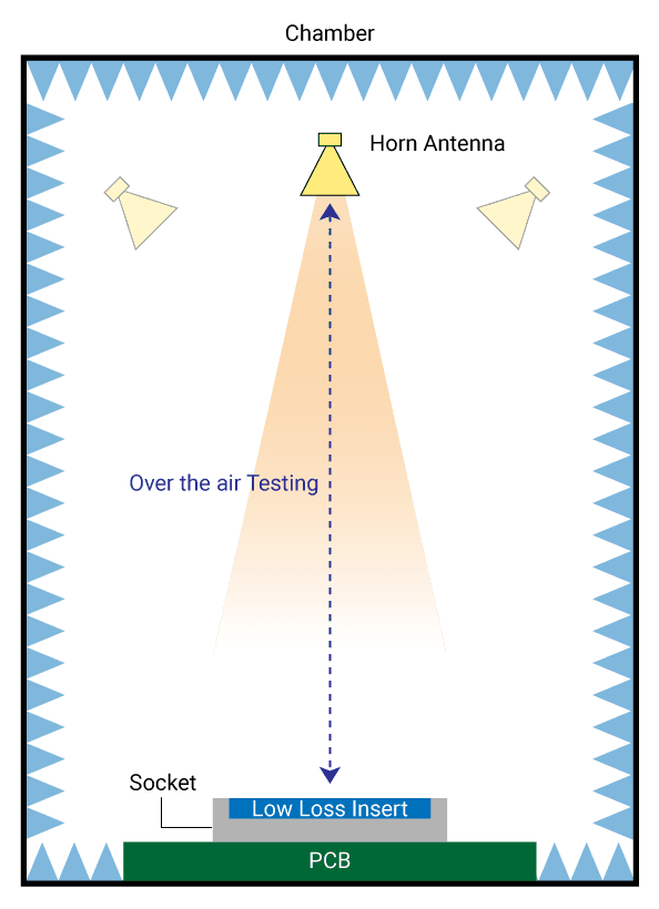 Figure 4 OTA testing using a horn antenna.
INNOVATIVE OTA TESTING SOLUTION
To address these shortfalls, TMYTEK has developed a phased array antenna testing method that is fast, has a small footprint and measures both power and phase. Since the antenna pattern is a critical element of a phased array antenna, identifying any gain loss or phase differences among elements is important, an aspect that traditional testing methods cannot perform efficiently in production.
TMYTEK’s XBeam system is available in two versions that scan antenna patterns in 2D and 3D in under 10 seconds—100x faster than other commercial test methods. It is compact and fully electronic, with no motors to limit measurements or cause interference. The small footprint makes it easy to integrate with other test elements such as handlers, and its application programming interface (API) and drivers support integration with existing test program configurations.Using TMYTEK’s UD Box up-and-down converter enables use of sub-6 GHz analyzers, eliminating the need for mmWave instrumentation. The innovative hardware and software design enables the system to provide an affordable total cost of ownership (TCO).
XBeam 2D
The XBeam 2D is the more economical version of the XBeam family, suitable for production line testing (see Figure 5). It is usually used for the small arrays used in mobile phones or customer premise equipment and also supports 2D testing of larger arrays, such as 5G radio unit and satcom terminals. The XBeam 2D receives and analyze one cut of the beam, generating a 2D pattern at ±5 degrees within 1 second. The radiation pattern is digitized, and the RF power data can be retrieved via the ethernet interface. For measuring other RF parameters, such as error vector magnitude (EVM), the XBeam 2D can be connected to a spectrum analyzer or universal auto tester via a 2.92 mm connector. The small box measures 30 × 15 × 8 cm.
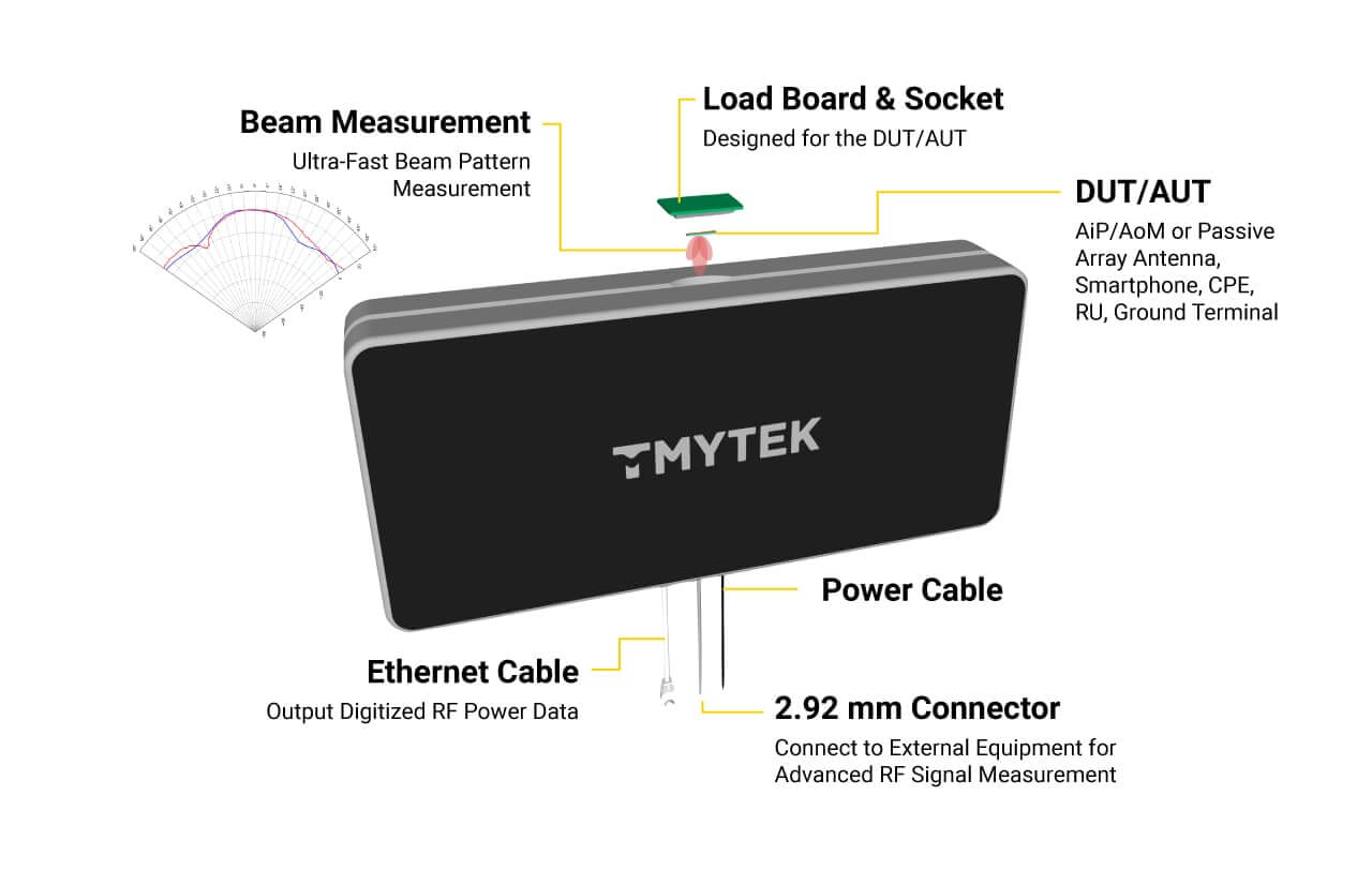 Figure 5 XBeam 2D test system.
To confirm the XBeam 2D’s measurement quality, TMYTEK tested and compared the XBeam 2D with a CATR under the same conditions using the mmWave New Radio beamforming development tool, BBox. The results (see Figure 6) show the peak gain and radiation patterns are similar, sometimes equal, whether the beam is at boresight or offset to a steering angle. The data confirms the XBeam 2D’s measurement method and results agree with the results achieved with a CATR.
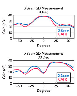 Figure 6 Pattern measurement comparison: XBeam 2D vs. the CATR.
A key feature of an AiP is beam steering, which has a baseline with all elements or channels having equal gain and phase. The OTA measurement system should be able to detect variations among the channels, which may indicate failures or the need for system calibration. To illustrate XBeam 2D’s ability to identify such issues, a 1 × 4 channel AiP module was measured with channels 1 and 2 purposefully adjusted for 3.5 lower gain and a -60-degree phase offset to simulate a defect. Figure 7 shows the measurement results, comparing the failures and good sections under the same test conditions. A single horn measurement system, which only measures peak gain at 0 degrees, would be unable to screen the non-functional components. By performing a full 2D pattern scan, gain differences can be noted when channel power is lower and the specific channel identified. With the phase offset, the beam has clearly shifted, and the AiP unit can be flagged by the test system.
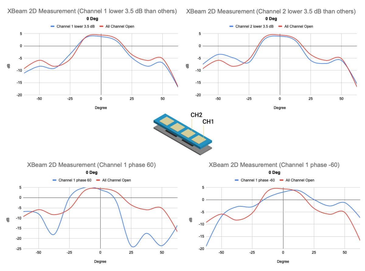 Figure 7 Measurements showing low gain and phase offset effects.
TMYTEK XBeam 3D
XBeam 3D extends the measurement capability to two dimensions, e.g., azimuth and elevation. The system comprises a specially designed shielding box and the TMYTEK BBox radio detector head in a 50 × 50 × 50 cm testing cube (see Figure 8). This first-generation module tests 28 GHz systems across ±50 degrees in 10 seconds.
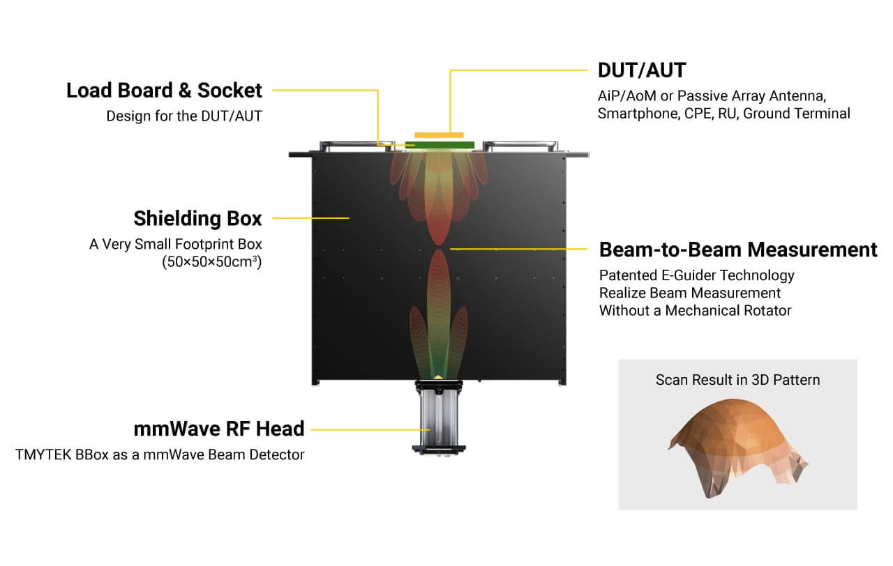 Figure 8 XBeam 3D test system.
The software developed for XBeam includes:
- BeamPicasso™, which measures beams at various angles
- mmWatson™, which measures and identifies faulty AiP modules
- OTACali™, which efficiently calibrates a phased array OTA.
The software can transform parameter measurements into visual bitmaps (see Figure 9). Piece-by-piece calibration and statistical analysis matures the database, improving the capability to identify defects accurately and quickly.
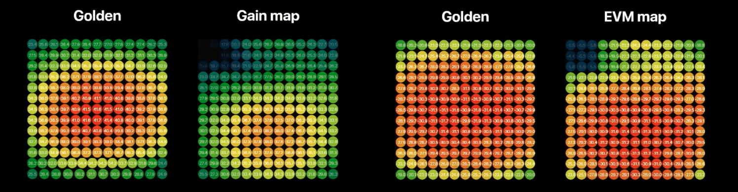 Figure 9 Parameter maps generated by the software engine.
To further improve capability and flexibility, handler APIs supporting popular wireless tester drivers enable the XBeam 3D to be fully automated in a mass production test system. Figure 10 shows test results with the XBeam 3D integrated with one auto tester. Gain and EVM were measured at three beam angles in under 2 seconds, with the beam pattern analyzed in real time to identify failures, so defective components can be flagged. Testing speed enables the measurement data to be collected and fed to a database for artificial intelligence (AI) modeling and intelligent analysis, correlating production batches with the characteristics of array elements, for example. Real-time processing improves production efficiency and provides feedback to design engineering teams.
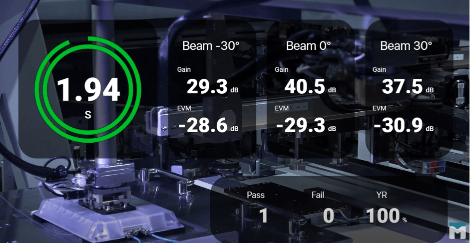 Figure 10 Demonstration measurements of the XBeam 3D integrated with auto tester.
Like the XBeam 2D, the 3D cube can be customized for testing different modules with various form factors and operating frequencies based on the same testing approach. Both version of XBeam are software driven and powered by AI. Table 1 summarizes the capabilities of the 2D and 3D versions of XBeam, and Table 2 compares the capabilities of XBeam to the CATR and horn antenna testing configurations.
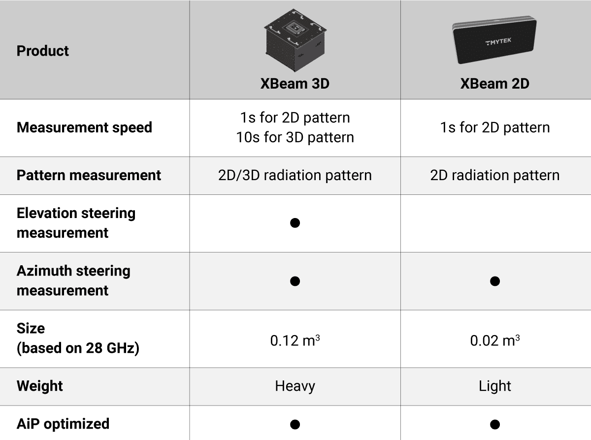 Table 1 Comparision of XBeam 3D and 2D.
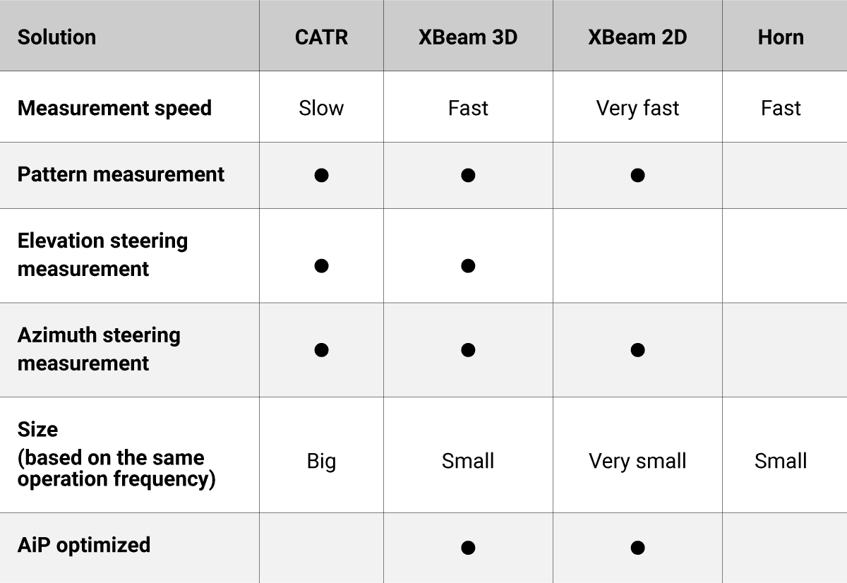 Table 2 The comparison of XBeam capabilities to the CATR and horn antenna testing configurations.
SUMMARY
The AiP is a key architecture for mmWave systems and devices, and the XBeam 2D and 3D test solutions offer a comprehensive way to test these systems. They can evaluate system performance—antenna patterns, EIRP, EVM—with the efficiency needed for production environments. Test times are typically 100x faster than can be achieved by traditional methods. With up- and down-conversion, the XBeam family interfaces with sub-6 GHz measurement instruments, further improving TCO. The XBeam test modules are compact and compatible with production handlers, and the AI-driven system software helps gain insight into AiP performance.