5G Channel Sounders: Ultra Fast Model Creation
POSTED ON JUNE 4, 2021 BY TMYTEK
As the massive deployment of 5G/B5G FR2 is just around the corner, research surrounding 5G FR2 mobile communication has already been extremely extensive. Researchers stress to provide the highest quality of working models for real mmWave communication. One of the challenges is to ensure the radio communication channels between 5G user equipments (UE) and base stations (BS) are passing the correct information through the channel at a high data rate. The difficulty, of course, increased with people working from home due to COVID-19. Nevertheless, the passion for improving the communication world is no less.
Channel sounding is the process of characterizing transmission channels by observing the transmitted impulse response at the receiver. However, the characteristics differ at different frequencies, bandwidths and data transmission conditions. In comparison to a traditional sub-6 GHz channel sounder, a mmWave channel sounder would have a much higher propagation loss and more susceptible to blockage or echoes due to distortions and reflections from buildings, or from weather elements. It is for this reason that creating mmWave channel sounder mathematical models become necessary and a must. With 5G FR2 running on the mmWave band, there is much to do on the research topic of channel sounders to overcome all the challenges.
North Carolina State University’s Communications and Signal Processing team led by Professor Ismail Guvenc is one of the top research teams on channel sounders. One of the research they have conducted is to characterize the channel sounder effects in 28 GHz mmWave bands using antennas and repeaters for non-line-of-site (NLOS) connectivities. This research is led by Dr. Ozgur Ozdemir from the same team.
Challenges
In Dr. Ozdemir’s channel sounding research, high propagation loss in mmWave system is one of the main issues that needs to be addressed. In order to build a better channel sounding model for mmWave bands, not only the power delay profile should be considered, the power angular-delay profile (PADP) should also be measured. The measurement begins by using high gain directional antennas such as horn antennas. The setup is shown in Figure 1. The NI mmWave Tx and Rx systems are both connected to an individual radio head for up/down conversion between IF and RF, then to a horn. The radio heads each sits on the gimbal for rotation. The impulse response is generated from the 10 MHz and PPS generator by a single rubidium (Rb) clock which is connected to both the Tx and the Rx systems.
The Tx and the Rx systems are placed 30 meters away from each other for the measurement. The test begins by rotating the gimbal so that the horn antenna is scanning the entire azimuth and elevation planes. The PADP measurement is done on every possible direction that the antenna points to. The directivity of the antenna and the speed of the gimbal rotation will be the key here because the total measurement time required depends on the number of positions that the antenna visited and the rotational speed of the gimbal. However, due to the mechanical nature of the gimbal, the speed is limited. Hence, an active phased-array antenna with high switching speed is required.
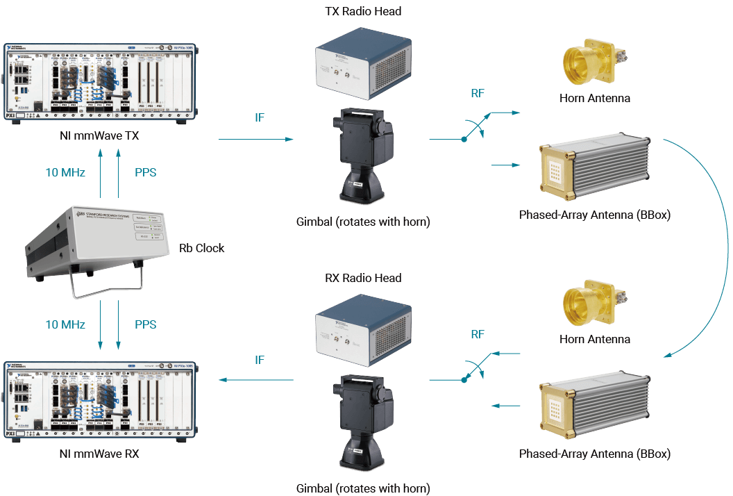 Figure 1. 28 GHz mmWave channel sounder hardware setup. Either horn antenna or phased-array antennas (BBox) are connected to the mmWave radio heads.
Solutions
TMYTEK’s BBox One has a high transmitter and receiver gain at typical values of 44 dB and 34 dB, respectively. The antenna 3 dB beamwidth is 28 degrees in the azimuth plane and 26 degrees in the elevation plane. It is capable of steering the beam at 5 degrees resolution from -45 degrees to +45 degrees in both horizontal and vertical directions. The product brief can be found on Figure 2.
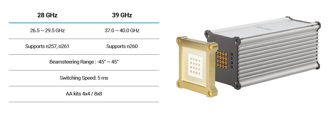 Figure 2. BBox One product brief
With the change from the combination of horn antenna and gimbal to an active phased-array antenna, BBox One, the scanning technology can be advanced from mechanical to electrical. The electrical scanning method is much faster, in the orders of tens of milliseconds. In this case, the direction of the beam can be switched in 15 ms, giving a significant improvement over the measurement speed. In the traditional gimbal with horn antenna rotational method, each measurement takes around 1s. With the phased-array BBox method, the measurement time is decreased down to 15 ms. The resulting path gain is shown in Figure 3. Please refer to the reference section for further details on Dr. Ozdemir’s research.
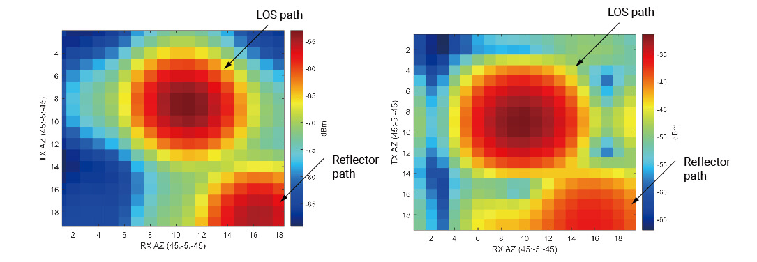 Figure 3. Total Received Power: horn antenna && BBox One
Benefits
Furthermore to the results shown above, for a complete case measurement, the horn antenna would take 43 min to complete, while the BBox would only take 1.4 min. It can be seen that as measurement data increases, the total measurement time becomes very critical. In this case study, TMYTEK has successfully supported NCSU for the demonstration of the benefits of BBox as compared to traditional gimbal measurement. For higher throughput and greater bandwidth channel sounder measurements, BBox would be a great choice.
Reference
Ozdemir, O., Erden, F., Guvenc, I., Yekan, T., & Zarian, T. (2020). 28 GHz mmWave channel measurements: A comparison of horn and phased array antennas and coverage enhancement using passive and active repeaters. arXiv preprint arXiv: 2002.00121.