Tile-Up RIS at 28 GHz: 2×2 Reflection Distance Extension Based on Programmable RIS Pattern Control
Cover. L-shaped corridor test site: short leg (5 m) for incident path, long leg (20~50 m) for reflection distance.
Overview:
Millimeter wave coverage extension in 5G
Millimeter wave (mmWave) communication at 28 GHz offers high data rates but suffers from high path loss and limited diffraction around obstacles. Reconfigurable intelligent surfaces (RIS) can redirect incident energy toward a target receiver, effectively extending coverage along non-line-of-sight paths. As the reflection distance increases, the phase profile across the RIS aperture must be updated to keep the reflected beam focused on the receiver. Therefore, programmable pattern generation and per-distance calibration are essential for real-world deployment.
Looking to build your mmWave testbed? Explore [ Smart Reflector: RIS Testbed Solutions ] ➔
While a 2×2 tile-up array (four modules, total aperture ≈ 434 mm) has a far-field boundary RFF ≈ 2D²/λ ≈ 35 m at 28 GHz. Beyond this distance, a larger effective aperture is expected to maintain higher gain toward a fixed reflection point than a single tile, provided that the phase pattern is recalculated for each setup of reflection distance.
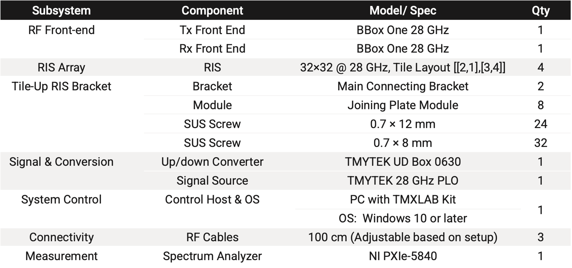
TMYTEK Tile-Up RIS stitches multiple 28 GHz RIS panels into a unified aperture with coordinated pattern upload through the TMXLAB KIT. For researchers validating coverage extension, having equipment that supports distance-dependent pattern generation, multi-module verify, and repeatable field measurement is necessary. This application note documents a field experiment that quantifies how much receive power improvement the 2×2 configuration delivers over a single tile as reflection distance is measured from 20 m to 50 m.
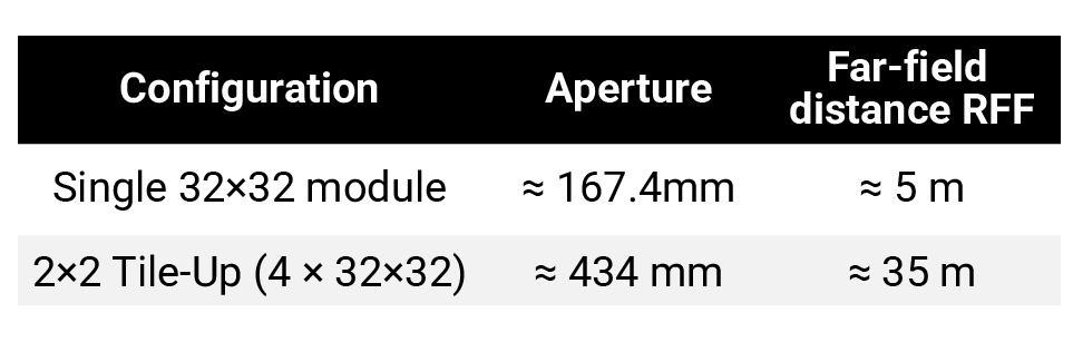 Note: Aperture D = (N−1)×5.4 mm = 167.4 mm per 32×32 tile (element center span). 2×2 total = 2×167.4 + 99.6 mm inter-tile gap = 434.4 mm. RFF ≈ 2D²/λ, λ ≈ 10.7 mm @ 28 GHz.
System Architecture
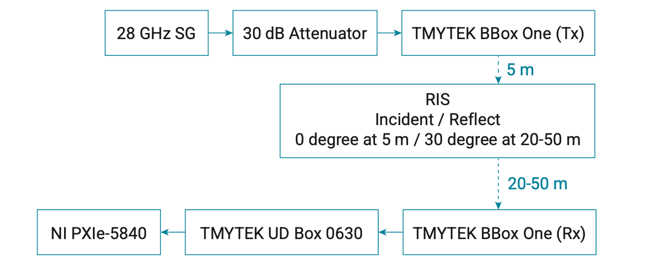 Figure 1. System Architecture
Explore Hardware Specifications: [Learn More: BBox 5G ➔] or [Learn More: UD Box 0630 ➔]
Experiment
We designed the following experiment to demonstrate distance-dependent RIS pattern control and to compare 2×2 tile-up gain against a single-tile baseline at each reflection distance.
The measurement chain uses a BBox One as a receiver at the reflection point, a UD Box configured for down-conversion with fixed center frequency (constant IF attenuation), and an NI PXIe-5840 for peak power readout.
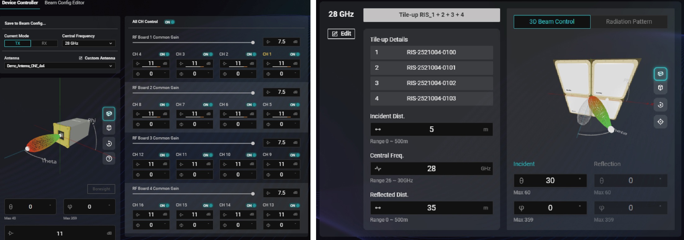 Figure 2. Control and measurement interfaces between RIS modules, host PC, BBox One Rx and UD Box up/down converter.
Experiment setup
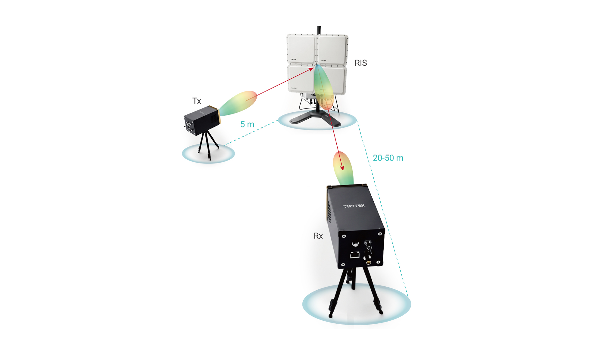
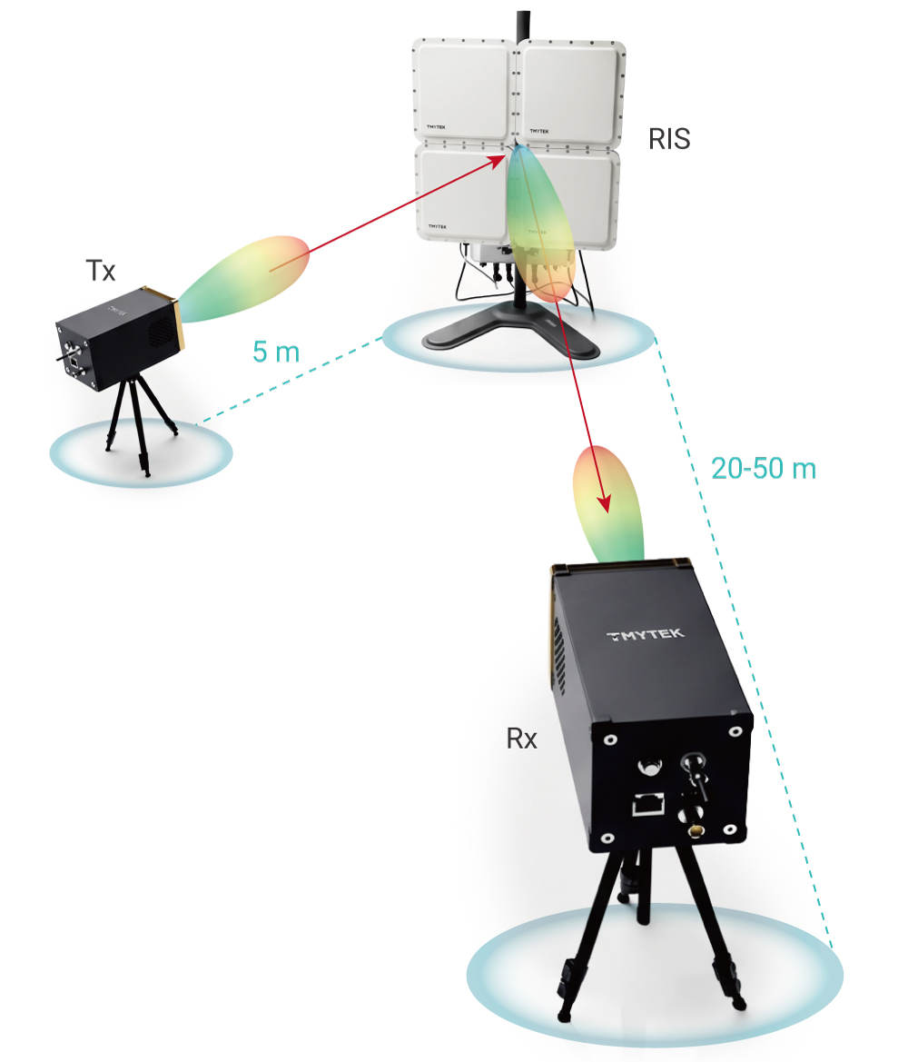 Figure 3. Experiment setup diagram — Tx on short leg, RIS at corner, Rx on long leg at distance Rr along θr = 30°.
Measurement Procedure
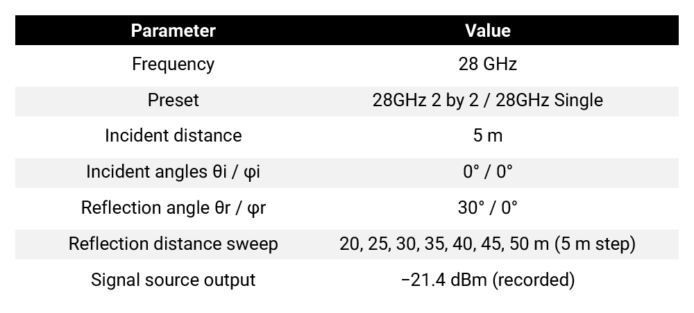
- Place Tx on the short leg at Ri = 5 m, normal incidence (θi = 0°, φi = 0°).
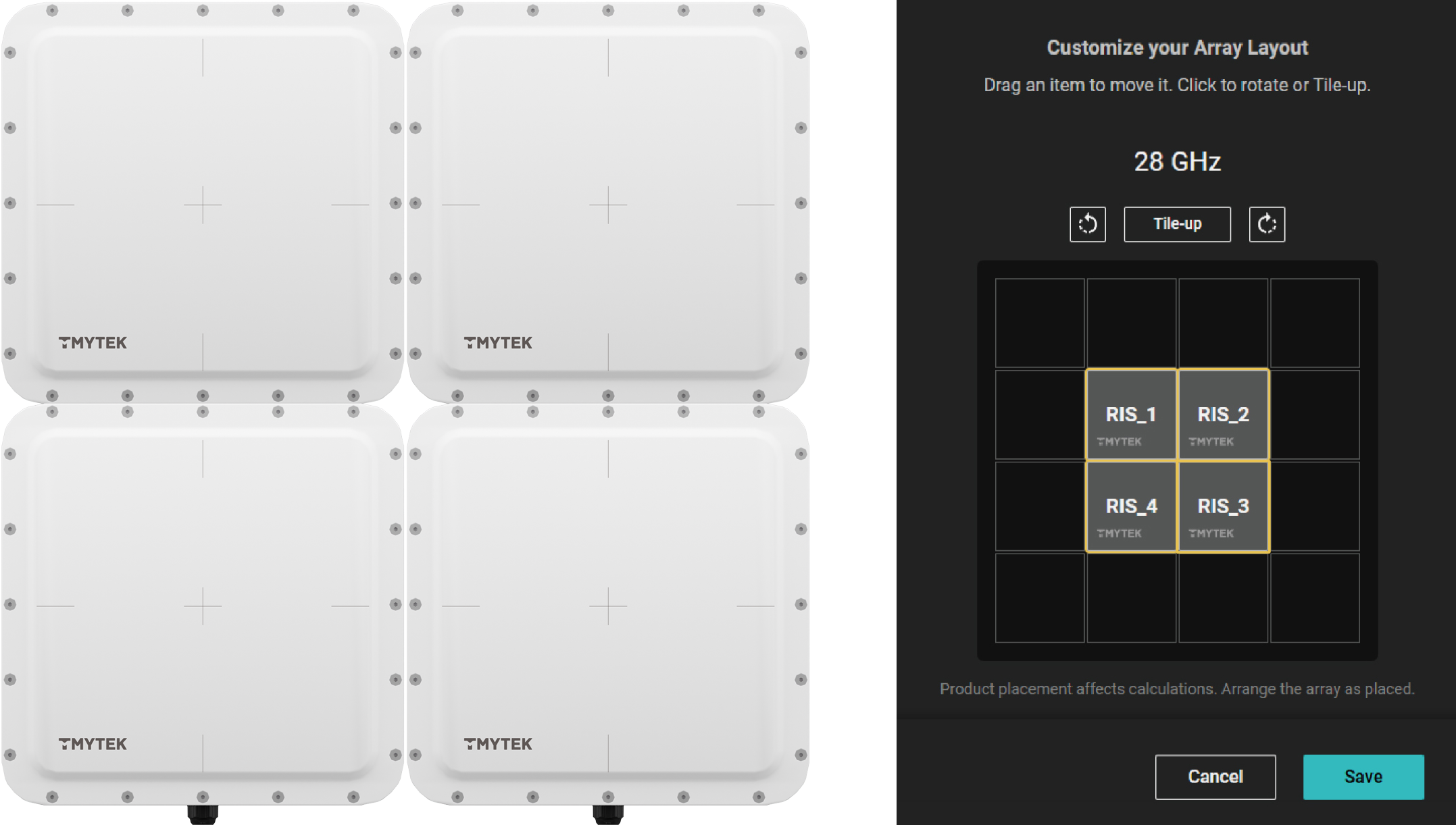
- Mount the 2×2 RIS at the corridor corner; confirm tile layout [[1,2],[4,3]].
- Position the RX BBox One at reflection angle θr = 30°, φr = 0°; set physical reflection distance using laser ranging.
- For each condition: set reflect_distance and incident distance.
- Record peak power (dBm) at NI PXIe-5840.
- Switch to 28 GHz Single preset; repeat steps 3–5 for the 1×1 baseline.
- Compute Delta (dB) = Peak2×2 − Peak1×1.
Discover the hardware behind programmable beam steering: View [ Dynamic RIS 28 GHz ] Product Specs ➔
Verify reflection-distance sweep
Table 1 lists the Phase 2 field measurement results. Positive Delta indicates higher received peak power with 2×2 tile-up than with a single module at the same geometry.
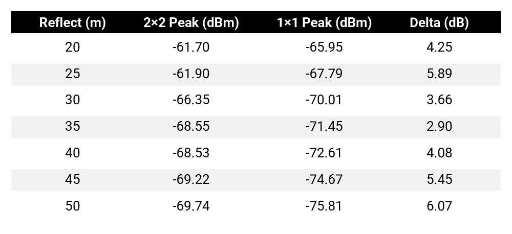 Table 1. Phase 2 distance sweep — peak power @ NI PXIe-5840.
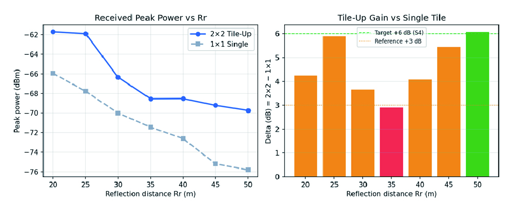 Figure 4. Received peak power (left) and tile-up delta (right) vs reflect distance Dashed lines: +6 dB target and +3 dB reference.
The 2×2 configuration maintains higher peak power than the single tile across all seven distances. Delta ranges from 2.90 dB to 5.89 dB, with the maximum at Rr = 25 m. Both configurations show gradual roll-off beyond 25 m, consistent with increasing path loss along the long leg. Near RFF ≈ 35 m, delta reaches a local minimum of 2.90 dB, then increases to 4.08 dB and continues increasing up to 6.07 dB at 50m.
Summary
This experiment demonstrates that TMYTEK Tile-Up RIS with per-distance pattern regeneration extends measurable reflection gain along a 50 m corridor. Compared with a single 32×32 module, the 2×2 tile-up array delivers approximately 2.9-6.07 dB higher peak received power for Rr = 20–50 m under fixed θr = 30° and Ri = 5 m. The best operating point in this dataset is reflection distance = 50 m (6.07 dB delta), suitable as a reference for follow-on studies (e.g., dual-reflection or time-division multi-UE scenarios).
For developers building mmWave coverage solutions, the results confirm that larger effective aperture plus distance-aware phase control is necessary when the receiver moves deep into the far-field of the tiled array.