
FR3 Horn Antenna
8-13 dBi Gain, 6-30 GHz Ultra-Wideband Dual-Polarization
Key Features
- Operating frequency 6 to 30 GHz
- Dual and linear polarization
- High port isolations and cross-polarization rejections
- Open Boundary Quad-Ridged structure
- 2.92 mm coaxial connectors
- Flexible mounting stand
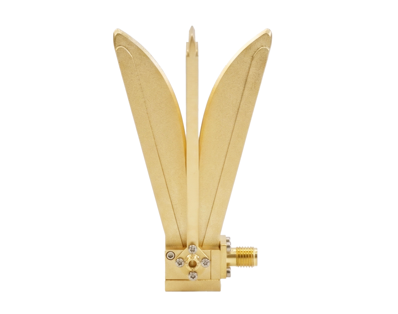
Why TMYTEK's FR3 Horn Antenna?

6-30 GHz Ultra-Wideband Coverage
A single antenna spanning Sub-6G through FR3 to mmWave—test across all B5G and 6G candidate bands without ever switching antennas.
Stable 10 dB Gain Across the Full Band
Broadband-balanced gain with minimal variation from 6-30 GHz, ensuring consistent measurements across all test frequencies.
Dual-Linear Polarization & 25 dB Isolation
Captures horizontal and vertical waves simultaneously via two 2.92 mm ports, cutting MIMO/OTA test cycles by 50% with pristine cross-pol discrimination.
Electrical Specifications
| Parameter | Conditions | Unit | Min. | Typ. | Max. |
|---|---|---|---|---|---|
| Frequency | --- | GHz | 6 | 18 | 30 |
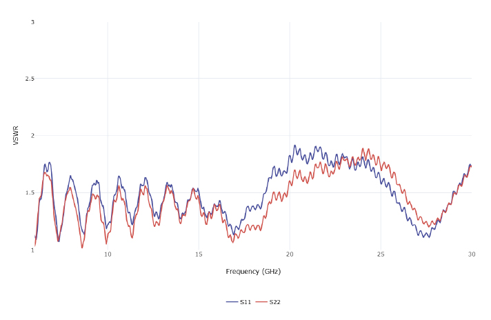
| Return Loss | --- | dB | --- | 10 | --- |
| VSWR | --- | --- | --- | 1.93:1 | --- |
| Gain | --- | dBi | 8 | 10 | 13 |
| Port Isolation | --- | dB | --- | 25 | --- |
| Cross-Polarization | --- | dB | --- | 25 | --- |
| 3 dB Beam Width | Horizontal Plane | deg | 22 | --- | 68 |
| Vertical Plane | deg | 17 | --- | 39 | |
| Weight | --- | g | --- | 87 | --- |
FR3 Horn Antenna Test Architecture
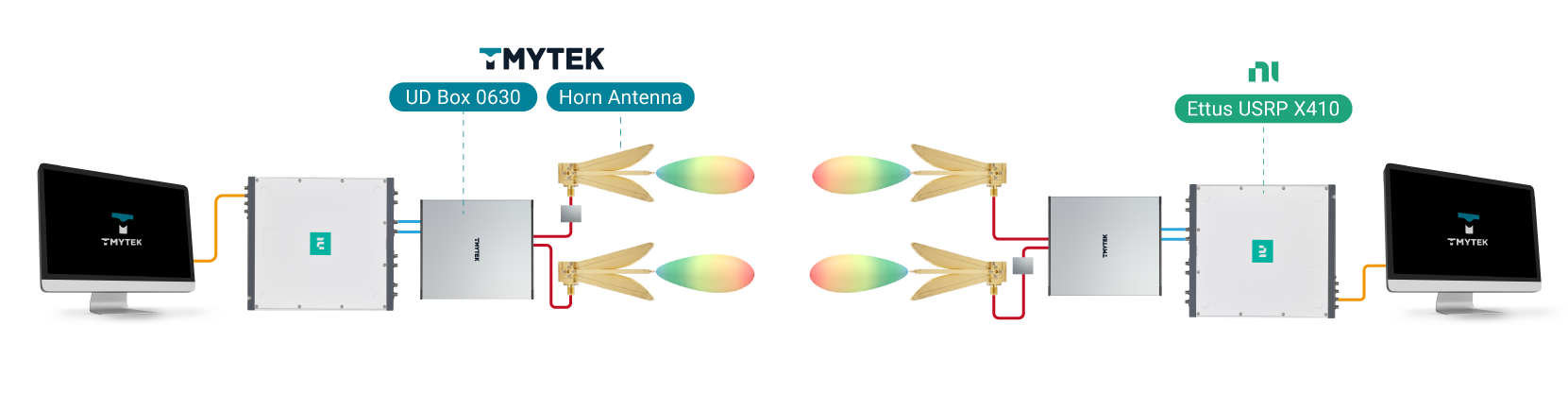
The FR3 Horn Antenna pairs with TMYTEK's UD Box frequency converter and can be integrated with mainstream SDR platforms such as the Ettus USRP X410 to form a complete FR3 wideband test chain covering 6-30 GHz. Unlike active phased-array systems, the Horn Antenna is a passive, dual-linear polarized front-end — it delivers stable gain and polarization diversity across the full band without beam steering or beam switching, making it well suited for calibration, link budget verification, and broadband channel characterization.
Signal Chain
The UD Box 0630 sits between the SDR baseband instrument and the Horn Antenna, performing up/down frequency conversion so the antenna's full 6-30 GHz range is accessible regardless of the connected SDR's native frequency coverage. As shown in the diagram, the Horn Antenna interfaces directly with the USRP X410 via 2.92 mm coaxial connectors.
FR3 Horn Antenna Introduction
Typical Performances
Return Loss
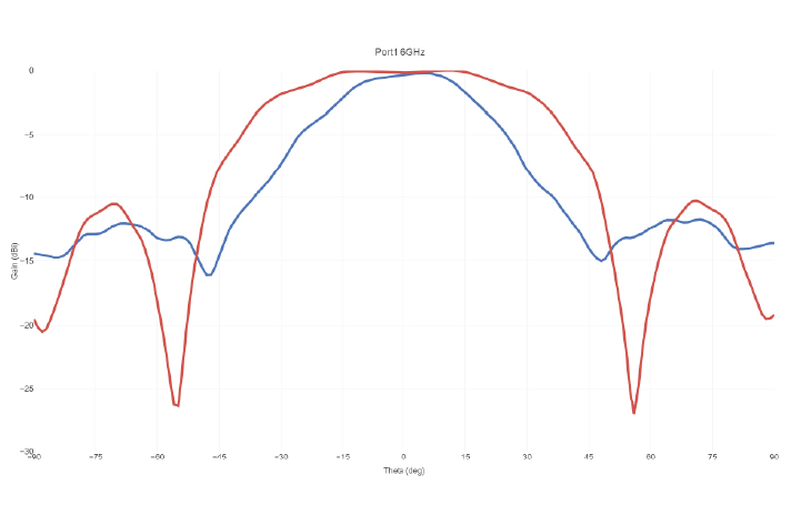
Radiation Pattern
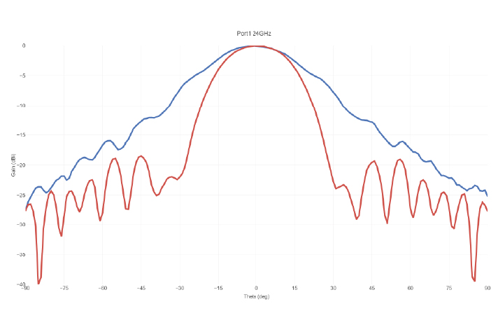
Radiation Pattern
Horn Antenna Series
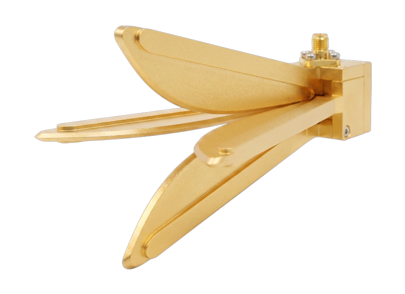
FR3 Horn Antenna
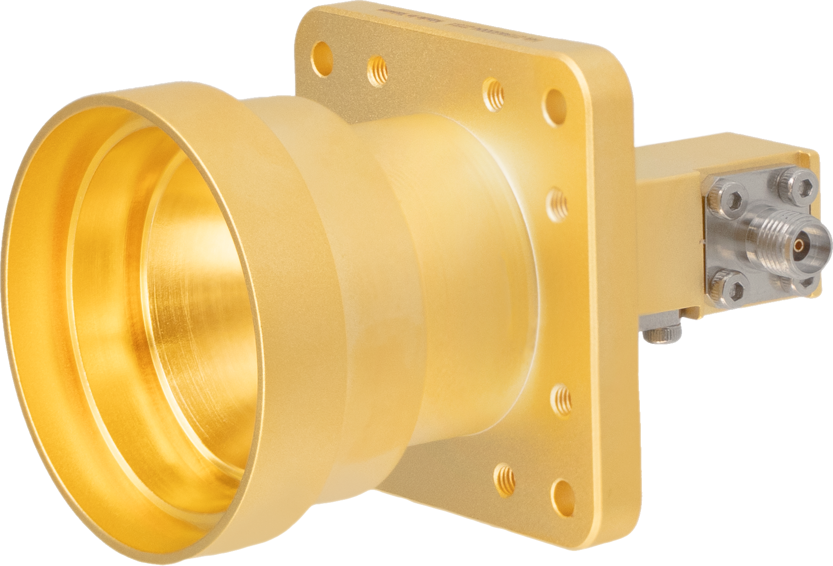
Target Application
Antenna Type
Frequency Range
Typical Gain
Typical Port Isolation
Cross-Polarization
3 dB Bandwidth
RF Connectors
Material & Finish
Product Weight
Dimension (L × W × H)
Datasheet Download
B5G / 6G FR3 Advanced Ultra-Wideband Measurement
Open-Boundary Quad-Ridged Structure
6 - 30 GHz
10 dB (Broadband balanced and stable gain)
25 dB (Excellent dual-channel balance)
25 dB
Horizontal-Plane: 22° - 68°, Vertical-Plane: 17° - 39°
Dual 2.92 mm Female (K-type), (Independent H/V ports)
Premium Aluminum
87 g
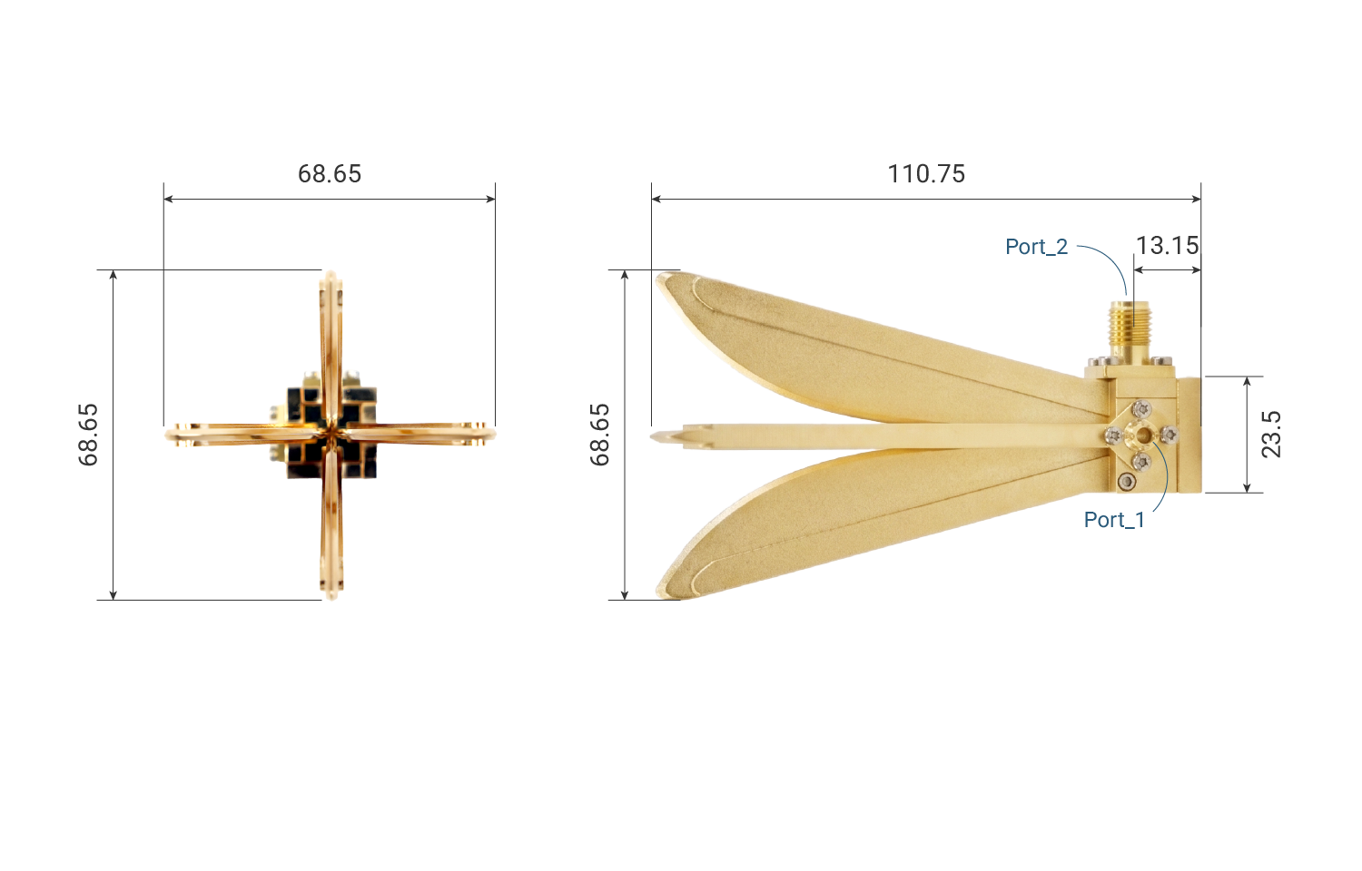
110.75 × 68.65 × 68.65 mm
5G FR2 mmWave Dedicated Measurement
Corrugated Conical Structure
25 - 31 GHz
17 dB (Highly focused beam)
35 dB (Extreme Isolation)
30 dB
18°
Dual 2.92 mm Female (K-type), (Independent H/V ports)
Aluminum
85 g
74.5 × 46 × 46 mm